Session 6: Conditioning with
Synchro blocks
We have already seen that all the blocks in a Scicos diagram need not
have the same activation time sets. A diagram containing time-dependent
blocks, which are always active, and a block driven by an event clock is
an example. We have also seen that a diagram can have two independent sources
of events driving each different blocks. Another situation that multiple
activation times arises is when conditioning is used.
Synchro blocks are used to condition block activation. Specifically,
a synchro block routes events received on its input activation port to
one of its output activation ports. The selected output activation port
depends on the value of the regular input of the block.
Construct the following diagram
by copying blocks from the palettes
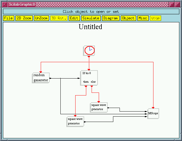 Conditioning in Scicos: If-then-else
is a Synchro block
The If-then-else routes
the incoming activation signal (in this case the events received from the
clock) to one of its output activation iports. If the input (i.e. the output
of the random generator
block) is positive, it routes it to the first output activation port, otherwise
it routes it to the second port. The random
generator generates a random value everytime it is activated.
The block parameters determine the properties of the random variable (Gaussian,
uniform, mean, etc...). The square
wave generator block
copies its internal state to the output and changes the sign of its
internal state everytime it is activated.
Set block parameters and simulate
Select the
Gaussian option for the random
generator. Modify
MScope
parameters to obtain 3 inputs
and set the display style to symbols. simulation result for Clock
period of 2 is given below.
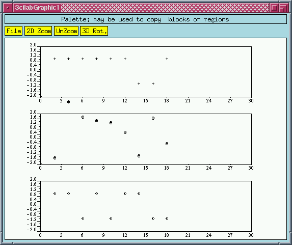 The MScope display
Note that the blocks of this diagram are activated only at event times
(except for the constant 1 block which is only activated once at initialization).
The Plus (+) block is not explicitely activated
by an activation signal, but it inherits its activation times from
its input signals, and in particular the Plus
(+) block in this case. In general, a block with no input activation ports
is either active permanently if it is time-dependent or it inherits
its activation times from its input signals. In this latter case,
its activation times are the union of the activation times of its input
signals. As for time-dependent blocks, we have already seen the sinusoid
generator. These blocks, even if they have inputs, they
don't inherit from them; they simply are always active.
Modify the diagram as follows
It is natural
to consider now conditional events loop, for example a counter which counts
and then stops at zero. There are however specific problems with that which
we shall see here.
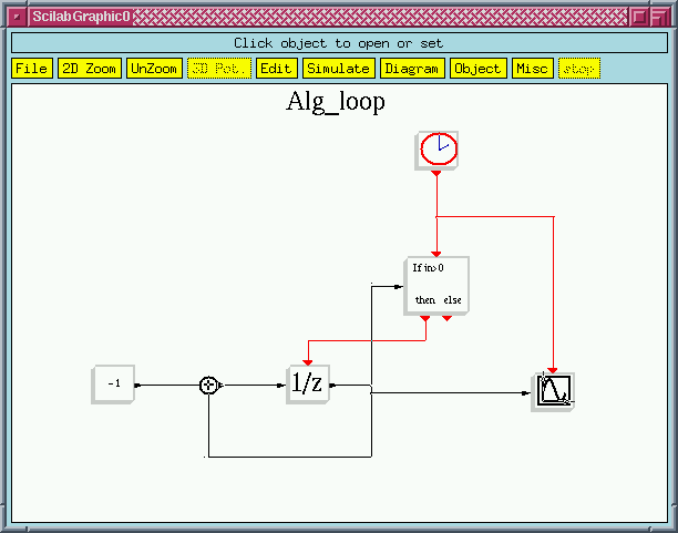 This diagram is not valid and the compiler signals an algebraic
loop
The problem here is that in order to decide whether the If-then-else
block should route the incoming event to the then
port or the else port, we need the value of
the output of the 1/z
block. But this output depends on the event coming (or not coming) from
the If-then-else block.
This is an indeterminism which we call an algebraic event loop.
It may seem that the 1/z
block, which is in a way a delay block, should break the loop. But it doesn't.
The reason is that the 1/z
block functions as follows:
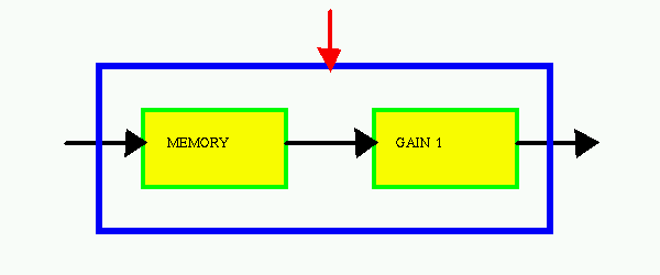 The inside of the 1/z
block
As we can see in the above picture, when the 1/z
block is activated, first the content of the memory
is copied to the output and then the input is copied to into the memory.
So there is no immediate relation between the input and the ourtput but
there is one between the input activation signal and the output. So in
order to break the loop, we need to make the output of the MEMORY block
available outside the block. This however is not possible in a regular
block. That is why in Scicos there is a specific block called Mem
(in the Others
palette) which does just that.
Modify the diagram as follows
To see the
inheritance mechanism, two independent event sources are included in the
diagram. The period of the second clock is also set to 2 but the initial
time is changed to .3 (from 0).
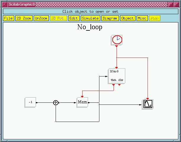 This diagram has no algebraic loop and compiles
If we intialize the Mem content to a positive value, at every clock
event this value is decreased by 1 until it becomes zero. From then on,
clock events are diverted to else output activation port of the If-then-else
block and Mem remains inactive.
Simulate the diagram
The Mem
is initialized to 10. The simulation
goes on up to the final time defined in Setup
of the Simulation
menu. It is possible to stop the simulation when 0 is reached by connecting
the else port of If-then-else
to a Stop
block (Event
palette).
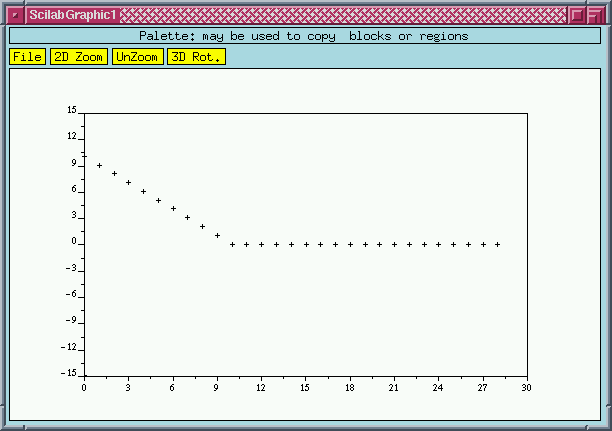 Scope output
Ready to go on?
For more information about Scicos, send an e-mail to Doctor Scilab:
Scilab@inria.fr
For suggestions about this Web server, send an e-mail
to Scilab@inria.fr


