Session 5: discrete systems and
inheritance
We have already encountered discrete-time blocks. A block is discrete
if it is activated by events and thus generates a piece-wise constant signal.
These events need not be evenly spaced in time. Diagrams can be made solely
based on discrete blocks.
Construct the following diagram
by copying blocks from the palettes
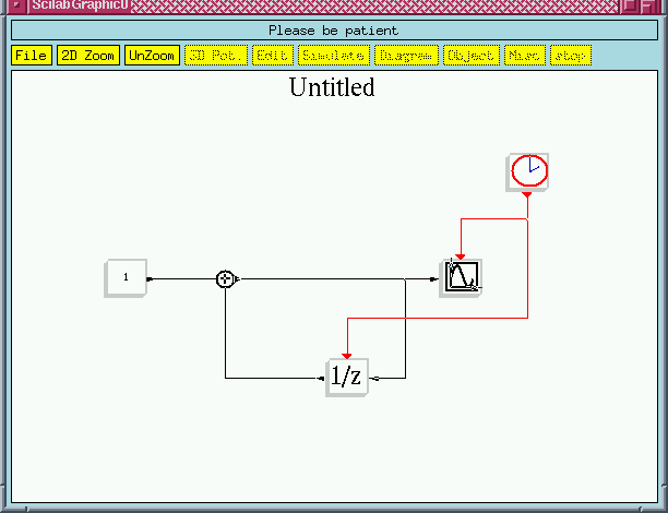 Purely discrete Scicos diagram
The 1/z (discrete
delay) is a shift register. Everytime this block receives an event (is
activated) it copies its internal state to its output and copies its input
into its internal state. This diagram is then a counter; at every Clock
event, the state of the register is increased by 1. In the case of discrete
signals, it is natural that the Scope
displays the signal using symbols and not a continuous line. This can be
done by changing Scope
parameters.
Simulate
The simulation
result for Clock period
of 2 is given below.
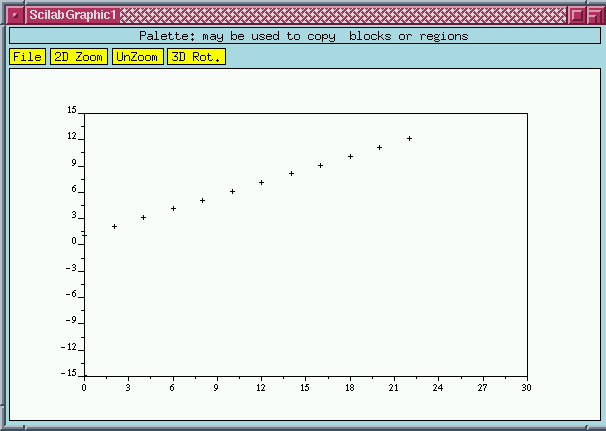 The Scope display
Note that the blocks of this diagram are activated only at event times
(except for the constant 1 block which is only activated once at initialization).
The Plus (+) block is not explicitely activated
by an activation signal, but it inherits its activation times from
its input signals, and in particular the Plus
(+) block in this case. In general, a block with no input activation ports
is either active permanently if it is time-dependent or it inherits
its activation times from its input signals. In this latter case,
its activation times are the union of the activation times of its input
signals. As for time-dependent blocks, we have already seen the sinusoid
generator. These blocks, even if they have inputs, they
don't inherit from them; they simply are always active.
Modify the diagram as follows
The Scope
block can also inherit its activations times. The input activation port
of this block can be removed by setting the corresponding block parameter.
Note that this input should not be connected when the port is removed.
The simulation result in this case is identical to the previous case.
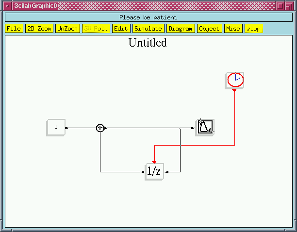 In this case, the Scope
inherits its activation times
Modify the diagram as follows
To see the
inheritance mechanism, two independent event sources are included in the
diagram. The period of the second clock is also set to 2 but the initial
time is changed to .3 (from 0).
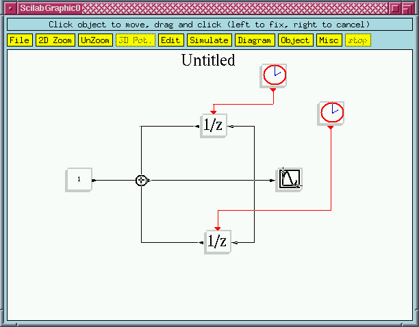 This block has two independent event clocks.
In this case, there is no risk of indeterminism because there are never
two independent events having the same time (in which case, one can be
fired before or after the other one). But this is based on the numerical
values of clock parameters; changing these parameters can yield indeterminism.
This type of diagram should be avoided, especially since similar result
can be obtained differently as it will be seen later.
Simulate the diagram
Note that the activation
times of the Scope
is the union of the activation times of the two registers, i.e., the union
of all the event times generated by the two event
clock's.
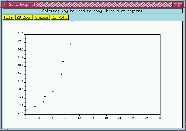 Scope is
activated at times 2n and 2n+.3, n=0,1,2,...
Ready to go on?
For more information about Scicos, send an e-mail to Doctor Scilab:
Scilab@inria.fr
For suggestions about this Web server, send an e-mail
to Scilab@inria.fr


