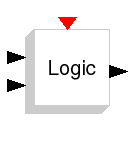
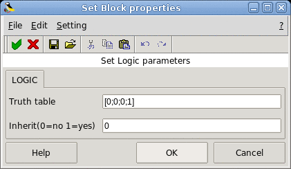
This block implements a standard truth table for modeling programming array, digital circuit and any other boolean expressions. The user can specify a matrix that defines all the possible block outputs in the Truth table field. Each row of the matrix contains the output of a different combination of input elements. The number of rows must be a power of two; it defines the number of inputs using the equation:
number of row = 2 ^(number of input)
The number of outputs is equal to the number of columns of the matrix.
This block supports only the int8 data type. When the input is positive, the input is considered as logical 1, When it is negative or zero it is considered as logical 0.
This block can be activated by an input event or it can inherit the clock from the regular input.
This block is used to implement SR and JK flip-flops.
The easiest example to consider is the OR example.
In this case we have two inputs and only one output.
The truth table for this example is [0;1;1;1].
|-----------|-----------|-----------|
|  input 1  |  input 2  |  output   |
|-----------|-----------|-----------|
|     0     |     0     |     0     |
|-----------|-----------|-----------|
|     0     |     1     |     1     |
|-----------|-----------|-----------|
|     1     |     0     |     1     |
|-----------|-----------|-----------|
|     1     |     1     |     1     |
|-----------|-----------|-----------|