Session 3: Zero-crossing
Below, we present a simple Scicos session to illustrate the use of zero-crossing
blocks.
We have already seen that events activate blocks, in particular we have
encountered the Event Clock which generated a trail of evenly spaced (in
time) of events which were used to activate the scope. A zero crossing
or treshold block generates events at times when the regular input of the
block crosses the value zero. It is possible to condition it also on the
direction in which the zero is crossed.
Open an empty Scicos
diagram
For that you can select New
in the Diagram
menu.
Construct a diagram by copying
blocks from the palettes, see following figure
 Scicos diagram with zero-crossing
The +to- block
is found in the Treshold palette, S/H
(sample and hold) block is in the Linear palette
and the cos block
is in the Non linear palette. We have already
seen the other blocks in previous sessions. Note however that the
MScope has 3 inputs here. The number of the inputs of the MScope is a parameter
of the block; it should be set before any of the inputs are connected.
The +to-
block generates an event everytime the input crosses zero with negative
slope (goes from positive to negative). The input must be continuous function.
The generated events activate the S/H
block which copies the value of its input (samples) and copies it to its
output. The output remains constant until the next time the block is activated.
Simulate
The simulation
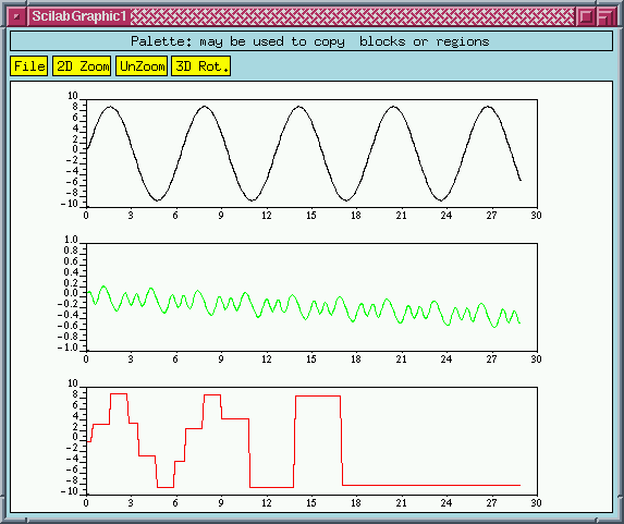
result is given below. The amplitude parameter of the sinuoid
generator block is set to 8.7
and the parameters of the MScope
are adjusted accordingly.
 The MScope display
The events generated by the zero-crossing block are used to generate
discrete signals. These discrete signals can be fed back to drive the continuous
component. This is typically what happens in a control system where discrete
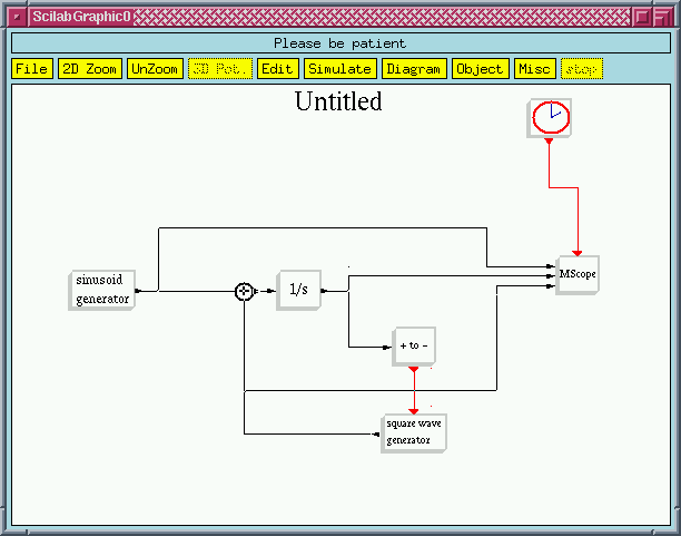
controllers control continuous systems. The following is a simple example:
 Discrete signal is fed back to the continuous part
Note that the square wave generator
has its output on the left hand side (in the Linear
palette, the output is normally placed on the right).
This is done using Flip
in the Editor menu.
This block has for output 0 and 1, the switch is made everytime the clock
is activated (i.e. it receives an event).
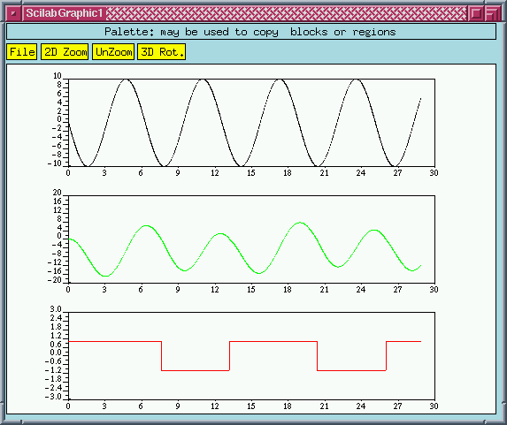
 The simulation result
Ready to go on?
For more information about Scicos, send an e-mail to Doctor Scilab:
Scilab@inria.fr
For suggestions about this Web server, send an e-mail
to Scilab@inria.fr


