Presentation of Scicos

Scicos: a dynamic systems modeler and simulator

www.scicos.org


Scicos is a Scilab toolbox included in the Scilab Package.  Written in Fortran, C and Scilab language, it comes with complete source code. Scicos provides many functionalities available in Simulink and SystemBuild.

Scicos is free software.


Scilab includes


Scicos and Scilab

Scicos is a Scilab toolbox and runs in the Scilab environment. Having access to Scilab functions when designing simulation models is of great importance.

  1.  Scicos user often needs to use Scilab functions such as those dedicated to filter design for signal processing or controller design in the construction of  simulation models.
  2. Scilab programming language can be used for batch processing of multiple simulation tasks, and more generally, models designed by Scicos can be used as functions in Scilab.
  3. Scilab graphical facilities can be used for post processing simulation results.
But the integration of Scicos and Scilab goes beyond that. Scicos editor is entirely written in Scilab language, this provides many advantages: There are disadvantages:

Scicos Formalism

Scicos provides an environment for designing reactive systems. Scicos models are designed using a block diagram editor, but an underlying language exists providing a well defined formalism.

This formalism is very simple because it deals exclusively with the reactive part of the design; it does not provide a complete programming language. The blocks are considered as atoms in Scicos; Scicos simulator considers them almost as black boxes. It knows some of their properties but not the underlying code.

The code realizing the behavior of a block (called the simulation function) can be written  in C, Fortran or Scilab.

In Scicos formalism, the execution of simulation functions are considered , instantaneous so  Scicos can be considered a Synchronous language or more specifically an extension of it to handle continuous time systems. The existence of a unique universal time is assumed in the formalism.

Scicos Block

A Scicos block can have two types of  inputs and outputs:
Regular inputs and outputs are used to communicate data from block to block through regular links. Activation inputs and outputs are connected by activation links which transmit control information (activation).

Example

Consider the following example which displays a random sequence and its delayed version on a multiscope.

Scicos diagram 1

There are four blocks here:
The diagram contains only one source of activation signal (the output of Delay). So all the blocks are synchronized and are activated simultaneously. This includes the MScope which is just a simple block and its activation implies reading the values on the inputs, placing them in a buffer and displaying.

Simulation result
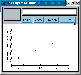
simulation result

Note that the first plot is a delayed version of the second plot; the delay is 3 units of time.

Multifrequency activation


An activation clock is simply an event delay with output fed back to its input. This generates a sequence of regularly spaced in time activation events. A multifrequency activation clock can be similarly constructed. For that, we use an event delay block with two output activation ports. The delayed activation is programmed once on one port then n-1 times on the other. n is a block parameter. See the following example:

Schema2

The red addition on activation signals represents the union of activation times.  The M.-freq-clock  block here has a delay of three and the parameter n is also set to 3. Thus this block, when activated, programs an event on its left output port for, for 3 units of time later. It does it again when reactivated. But the next time, it programs it on the right output port and the whole process starts aver again (this behavior is achieved using an internal state which starts from 1 and it is incremented at each activation until it hits n when it is set back to zero). By feeding back all the delayed events into the input activation port of this block, we end up with a multifrequency activation clock: the sum (union) of the two delayed activation signals is a regularly spaced in time sequence of events (with period 3), and the right output of the block generates also a regularly spaced in time sequence of events but with period equal to 9.

simu2

This example does not represent a synchronous system because there are two sources of activation signals. Sources of activation signals are considered asynchronous and an asynchronous diagram present in general non deterministic behavior. In this particular example however there is no nondeterminism possible as long as the delay in the
M.-freq-clock  block is strictly positive. Note that the two activation signals used for activating other blocks are synchronous. In particular the signal activating the 1/z block is a subsample of the signal activating the random generator and the MScope blocks.

Subsmapling

There are two conditional blocks in Scicos which implement conditioning. Even though they are presented and used as blocks in the editor, strictly speaking they are not Scicos blocks. They have no corresponding simulation functions and they are the only "blocks" that generate output activation signals synchronized with their input activation signals. The activation outputs of these block do not constitute independent and asynchronous sources of activation.

The two blocks should be compared  to the If-Then-Else and Switch statements in C, but of course the context here is very different.

The multifrequency behavior seen in the previous example can be achieved in a purely synchronous context using subsampling. In the following example, this point is illustrated. To make the example more interesting, the subsampling is not done based on a fixed frequency but conditioned. In particular, the activation for the 1/z block is generated only when the output of the random generator is positive.

schema3

The simulation result given below illustrates exactly what the system does.

simu3


This diagram is synchronous because it contains only one source of activation signal. Note that the If-Then-Else "block" is not a block as far as Scicos is concerned. It is represented as a block in the editor for convenience. The two activation outputs of this block are mutually exclusive and their sum (union of activation times) equals its input activation. In a sense, this block redirects the activation it receives in one or the other direction; it does not consume it as a Scicos block would.


Event Driven vs Data Flow

Strictly speaking Scicos provides an event driven environment. This means the activation of each block is explicitly determined by an activation signal.  However, through the inheritance mechanism, Scicos provides to some extent a data flow behavior as well.

Inheritance


Consider the following example.

inheritance

Here that unlike previous examples, we have blocks which do not have activation input ports. So how are they activated? The answer is: by inheritance. A block with no activation input port (and not always active, we shall see that later) inherits its activation through its regular inputs. The activation associated with a regular signal is the activation times of the block which has generated the signal. In this example we have only one source of activation, the Event Clock (Event Clock is not a block but a super block which includes a Delay block with a feedback as seen before). The Cos block inherits its activation from its regular input signal generated by the Square Wave Generator block. This latter is activated by the activation signal from the Event Clock, so due to the inheritance mechanism, we have that the Cos block is also activated by this activation signal. In fact we would have exactly the same model if the Cos block had an activation input port and the output of the Event Clock was connected to it.

The Summation and Scope blocks are also activated by inheritance. In fact, the 1/z block would also function the same way if it did not have an activation input port.  But if it does and it is not connected, the block remains inactive (no inheritance).


Inheritance and multifrequency


The inheritance mechanism is pretty simple to understand when a single activation exists in the model. With the presence of subsampling or in asynchronous cases, the inheritance still works following specific rules.

Let us start by noting that blocks in Scicos may have more than one input activation ports.


multi-input

The block Selector has two input activation ports. The block is activated by both activation signals. There are three activation scenarios possible for a block with two activation input ports:
The block knows by which way is has been activated. Selector uses this information to place on its output the first or the second input depending on the port through which it has been activated. In this case, the last scenario does not occur  because activation signals out of the If-Then-Else block are mutually exclusive.

It is now easy to see what the diagram does. The output of the Selector is the random signal generated by Random Generator block as long as the signal is negative or zero. If it is positive,  the output of the Selector is 1. Here is the simulation result.


sim

Note on this example the presence of the block Constant (=1). This block is not activated and it clearly cannot inherit any activation (absence of input); it is not declared always active either (more on the property of always active, later). Such blocks can only generate constant outputs because they are "activated" only once at the initial time (and possible reinitialisation in a special case discussed later).

Going back to the problem of inheritance consider the following example.

schema6

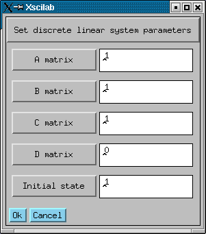
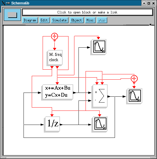
The parameters of  the M.-freq-clock block are chosen such that every 3 units of time it is activated once, and its activation goes once to the block realizing the discrete linear system and twice to 1/z block. The parameters of the linear system are:

gui


In this example the Summation and the Scope blocks all work by inheritance. The Scope blocks on top and at the bottom inherit clearly from the linear system and 1/z blocks. In such simple cases, this means that an activation input port is added to the block which inherits (in this case Scope) and its is  connected to the same activation source which is activating the block generating its regular input (linear system for the first Scope and 1/z for the second). The case of the Summation block is a bit more complicated; it inherits from two input signals. In this case, the inheritance mechanism creates two input activation ports for the block and connect them according to the sources of the regular inputs.  The way Scicos handles the inheritance in this case can be seen in the following diagram which is completely equivalent to the original diagram but where all the activations are explicit.

no_inh

The Summation block does not use the information available to him as to through which port  it has been activated (it could have).  Every time it is activated, it simply performs a sum (actually here a subtraction). It is activated every time the linear system block or 1/z is activated --its activation corresponds to the sum of the activations of these two blocks. This of course makes sense because the times where the sum operation should be performed corresponds to the union of times when its inputs may change. This in fact is the underlying justification for inheritance.

The last Scope inherits from the Summation. It has only one regular input port, so inheritance mechanism creates a single input activation port. This port receives the activations of the Summation block, i.e., the sum of the activations received on its two input activation ports.

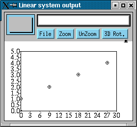
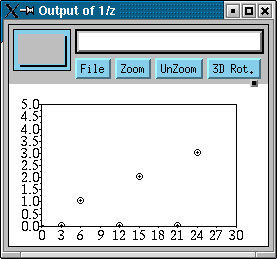
The simulation result illustrates how the scopes are activated due to the inheritance mechanism.
a b c


Continuous time and always active


A block can be declared always active. This means in particular that the block is a continuous-time block, i.e., its outputs and state can vary continuously. Normally, always active property should be designated by an activation signal received on an activation input port if we are to be consistent with Scicos formalism, however, to avoid useless complexity at the level of the editor, this property is simply specified as a block property.

There are a number of blocks in Scicos palettes which are always active. These blocks can be used with other blocks to construct hybrid diagrams.

cont


In this example the Sinusoid Generator and the integrator block 1/s have the always active property (not visible on the diagram, it is an internal property). The Abs block inherits this property. If 1/s did not have the always active property, it would have inherited it and the result would have been the same. In most cases,  an integrator without the always active property would work except in special situations for example when it is placed in front of a constant block.

The Event Clock here is simply used to fix the pace at which the MScope displays its input signals. The result is:

const-sim


Note that  the output of the continuous time block 1/s is connected directly to the input of the event driven block MScope. The value taken by the latter is simply the sampled value of the continuous time signal.

Continuous time and subsampling

Subsampling also works with continuous time signals.

cont


In this example, we again compute the integral of the absolute value of sin(t). This is done by selecting sin(t) or -sin(t) depending on the sign of sin(t).

The block S/H (Sample and hold) is not necessary here; the simulation result would be the same without it. We have used it to illustrate an important point in relation with inheritance. Without it, the block Multiply would be active all the time (inheriting from Sinusoid Generator). But now, it inherits from the Else port if the If-Then_Else block, which means that it is only active when sin(t) is negative. Of course in this simple example, that is not
so important. But if in place of the block Multiply we had a large number of complex blocks, the economy would be significant.

The simulation result shows the "inactivity" of Multiply when the result is not needed.


conts


Continuous discrete time interaction


Continuous time operations and discrete-time event dependent operations can interact in different ways.
  • Continuous and discrete time signals can be inputs to the same block. In fact fundamentally, there is no difference between a discrete time signal and a continuous time signal. In fact a Scicos signal can have discrete property over a period of time and later continuous property. This means that in Scicos we can perform operations (such as addition of) continuous and discrete time signals.
  • Continuous time signals can generate events through zero-crossing blocks
  • Events can create jumps in continuous time states
The following example shows some of the above points.

hyb

The blocks -to+ and +to-  are zero-crossing blocks which generate events when their continuous time input signals cross zero respectively with a positive and a negative slope. These events are used here in the Relay block to change the input of the integrator block 1/s. The simulation result is given below.

hybs


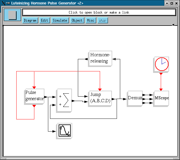
The following example shows how an event can be used to re-initialize a continuous time state. This example correspond to a model of  a hormone-releasing hormone pulse generator proposed in:
D. Brown et al., "Modelling the Luteinizing Hormone-Releasing Hormone Pulse Generator", Neuroscience, Vol 63, no 3, 1994.
Scicos diagram is courtesy of  Frédérique CLEMENT (INRIA Rocquencourt).


clement

The Jump linear system block realizes a standard continuous time system x'=Ax+Bu, y=Cx+Du, where u is its first regular input. When the block receives an event on its activation input port, the continuous state of the block jumps and takes the value of the second input of the block.

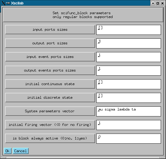
The Pulse generator is a user block constructed interactively using the block scifunc in the Scilab language. The scifunc block is very useful for rapid prototyping however the content is interpreted during simulation and thus can slow down the simulation. In this case, this block is parameterized as follows:

d1
Note here that the parameters of the block are defined symbolically. The actual values of mu, sigma... are given in the Context of the diagram. The behavior of the block is defined below.
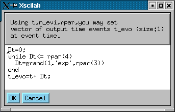
d2 d3

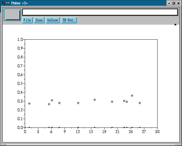
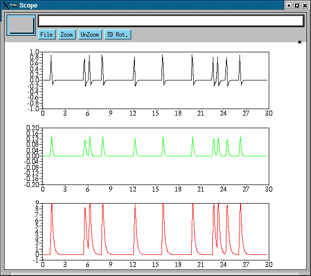
Note that the size and the timing of the pulses are obtained using the random number generator of Scilab, grand. The output of the Scope is:
imp

The output of the MScope is (we do not elaborate on the continuous time model used here so the simulation result is simply given to show the type of system we are dealing with and illustrate its hybrid nature).
hybd